Showing posts with label 3D print. Show all posts
Mar 21, 2025
Mar 19, 2025
Mar 17, 2025
Mar 16, 2025
Mar 13, 2025
HO scale Electromobile, Scranton
Electromobile" as built by Osgood-Bradley for the Scranton Railway Co / Scranton Transit Co. Full color printed HO model designed for Bowser drives.
https://interurban-models.myshopify.com/products/87-1401
Sep 1, 2020
3D-printed O-scale SnapTrack
Some free stuff for O-scalers:
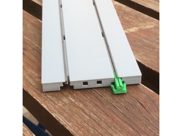
- Straight street track: https://www.thingiverse.com/thing:4255849
- Curved street track: https://www.thingiverse.com/thing:4585395
https://www.facebook.com/InterurbanModels/posts/729063004323976
Mar 8, 2020
Mounting the Cincinnati Wooden Combine on a Tomytec TM-21 drive
N scale resin printed car body with additional parts: a fine pilot, rear doorsteps and 2 dummy trolley poles.
The car is designed for motorization with a Tomytec TM-21 drive (truck centers 56.6 mm).
This Tomytec drive is nearly symmetrical, but it goes better into the carbody with the flywheel in front. The flywheel is hidden under a ballast block, but still visible
The rear platform and the pilot plug into the Tomytec frame, into the small holes in front and back.
Sometimes, the two holes in the Tomytec drive are to small, due to production tolerances, do not force them in. It is better to widen the holes with a 1.5 or 1.6 mm drill, and fix the pilot and the rear steps with a dot of glue.
There are several truck frames coming with Tomytec drive, two types are going very well for this car. On the rear truck, small parts of the truck side frame must be cut away on one side, to allow free swing of trucks under the door steps
Once the frame completed, the body will snap over the drive, and you can plug the two trolley poles into the holes. You can bend the rear pole up.
Painting: The cars were originally probably painted dark green, later some were painted orange. The roof were dark grey or brown, the under body parts black.
We recommend Valejo acrylic paints.
Jan 27, 2020
Tomytec Drive for Cincinnati Curved Side Cars
How to adapt a Tomytec TM-TR04 drive for Cincinnati Curved Side cars ( Speedrail, Dayton & Troy, ...)
Available here: https://interurban-models.myshopify.com/collections/n-scale-interurban-cars
1/ Modify the elongation of the drive to the maximum of 49 mm truck centers
2/ Select the short platform (S) extensions from the Tomytec add-ons
3/ Glue the pilot to one platform, put a weight in the second platform
4/ Clip the platforms into the drive, motor truck on rear.
5/ Choose truck frames KS45L or Brill (none is prototypical, but you wont detect it ...)
6/ Bend the dummy trolley pole up and plug it into the hole in the roof (diameter 1.2 mm)
7/ Clip the body over the drive.
When transporting, hold your hand under the car, the drive can sometimes fall out
Protect from heat and excessive sunlight

Available here: https://interurban-models.myshopify.com/collections/n-scale-interurban-cars
2/ Select the short platform (S) extensions from the Tomytec add-ons
3/ Glue the pilot to one platform, put a weight in the second platform
4/ Clip the platforms into the drive, motor truck on rear.
5/ Choose truck frames KS45L or Brill (none is prototypical, but you wont detect it ...)
6/ Bend the dummy trolley pole up and plug it into the hole in the roof (diameter 1.2 mm)
When transporting, hold your hand under the car, the drive can sometimes fall out
Protect from heat and excessive sunlight
Mar 25, 2019
THE "L" - Elevated Open Station 186 mm #160-0151

The system is based on Kato Unitrack/Unitram standards. The standard track centre distance is 25 mm, and the standard length of a sections is 186 mm.
The structures are made basically of three components, the spans , the cross bents, and the station decks. They are designed to be erected over standard Unitram sections.
Elevated sections can be connected directly with Unitrack/Unitram sections.
The construction requires some additional parts: Kato Flex track 21-000 and Kato UniJoiners 24-815.
You need also the following tools: Allen key, Plastic cement or AC glue, tools for cutting the flex rail, sandpaper, file
Before glueing parts, become familiar with the kit. Don't hesitate to ask questions.
Station cross bents:
The station cross bent is made of 5 parts: the top of the bent, two halves of the column gantry, and two column bases.
Assembling the cross bents:
The bents on the end of the station are made of one half bent with guards (blue) and another half of a standard station bent. There are also two types of bent tops: Type C25 for middle bents, Type D25 for end or connecting bents.
The center bents are made of two half standard station bents glued back to back.
Start with glueing the halves back to back. Sand the top of the column assembly and than insert and glue a Top of bent. Then plug the column bases onto the bottom of the columns. You can glue them, or keep them removable. The bents are now ready.
The spans
The standard span is single track 186 mm long, made of two twinned 93mm sections, with plate girder. Each span has two channels for the flex rails. Optional, you can add dummy 3rd rail.
Assembling the spans
The plastic part present small edges on top, this is inherent to the production process. We recommend to sand the top end of the spans a little. Then cut the rails 186 mm, or 372 if you want to join two station kits. Slightly sand the bottom ends of the rail profile, to avoid sharp edges. Push the tracks carefully into the channel of the spans, and plug one Kato UniJoiner on each track end, left side.
Station decks
The decks are made of 3 plastic parts and 2 laser cut wooden decks. Glue the inside girder frame, the central deck frame and the outside girder with its cast-in guards
The central frame is not symmetric, the wider spaces must be placed OUTSIDE, next to the girder with guards. Do not yet glue the wooden decks.
Staircases:
The staircases are made of three parts: the stairway with right guard cast in, the left guard, and small squares (red) to enclose the staircase on deck.
Once glued, the staircase and the guards and handrails form a solid unit. Sand the top sides of this assembly a little.
Assembling the Elevated sections
Plug the track spans into cross bents. Return the assembly and fix the bent to the spans with M1.6 screws. 2 screws for one bent are more than adequate. Tighten the screws with care, otherwise you destroy the thread in the plastic bloc. Then you can insert the station decks
Fixing the wooden decks:
The wooden decks are made of half sections, each is mirrored. There are several positions of the stairways possible. The unused hole in the deck is to be covered by the small cover plate, with or without glueing.
Inserting the Staircase:
Glide the staircase assembly into the deck. The middle of the stairway sits on small arms of the bents. You can remove unused arms later with a cutting knife, if you have decided how the staircases are mounted.
Adding 3rd Rail
Test the position of the 3rd rail before gluing, the small squares plug into the space between the sleepers on the the ends of a 93 mm sections. Choose the good distance to the track, my preferred value is 4 mm, inside rail to inside 3rd rail
Fixing to pavement or Unitram sections
You can fix the Elevated sections to your pavement or to Unitram sections with 1.6mm screws. The holes on the cross bents are 54 mm apart in width, the columns are spaced 93 mm in length.
Feb 17, 2019
THE "L" - Elevated railway kit - Curved sections #160-0136 and #160-0118
The system is based on Kato Unitrack/Unitram standards. The standard track centre distance is 25 mm, and the length of the sections is a multiple of 31 mm.
The structures are made basically of two components, the spans and the cross bents. They are designed to be erected over standard Unitram curved sections. Elevated sections can be connected directly with Unitrack/Unitram sections.
Bents and spans are fixed with screws, the assembly is modular and can be constructed / deconstructed.
Parts & Tools:
The construction requires some additional parts: Kato Flex track 21-000 and Kato UniJoiners 24-815.
You need the following tools: Allen key, plastic and/or AC glue, tools for cutting the flex rail, sandpaper, file.
We recommend to build only one 90° section a time, and to take care not to mix the parts unless you are familiar with the structure.
Assembling the spans for one 90° section
Both curved tracks use the same radius of 204.5 mm, the outer track has two straight sections of 25 mm on each end.
The inner curve is made of two 45° standard curved sections (yellow).
The outer track is made of one special 22.5° left section with 25 mm straight integrated (red), one 45° standard section (yellow) and a special 22.5° right section, mirror of the first one (red).
The plastic parts present small edges on top, this is inherent to the production process. We recommend to sand the top end of the spans a little. Glue the two 45° section together, and then the three parts of the outer track.
Take a length of Kato Flex track 21-000, file slightly the bottom ends of the rail profile, to avoid sharp edges. Push the tracks carefully into the channel of the spans, and plug one Kato UniJoiner on each track end, left side. We recommend to bend the track approximately to the radius without kinking the track.
Flex rail length for a 90° section (approx.)
- Inner track, inner rail: 314 mm
- Inner track, outer rail: 329 mm
- Outer track, inner rail: 364 mm
- Outer track, outer rail: 379 mm
Assembling the cross bents
There are 3 types of cross bents. The bents at position 0° and 90° are standard bents, same as on straight sections. The triangular bent at 22.5° has three columns and is the most complex one. The 45° bent is close to the 0° standard bents, but wider. The bent at 67.5° is a mirrored version of the 22.5° bent.
Standard bents:The standard cross bent is made of 5 parts: the top of the bent, two halves of the column gantry, and two column footers.
There are two types of bent tops: Type A for middle bents, Type B for end or connecting bents. You can use end bents "B" in place of middle bents "A", but not inverse.
Start with glueing the halves back to back. Sand the flat upside of the column assembly and glue it under the top. Then plug the column footers onto the bottom of the columns. You can glue them, or keep them removable. The bents are now ready.
22.5° Bent:
Glue the half gantries back to back, sand the flat upside.
Start fixing the full arch under the top, the small "nose" pointing inside the triangle. This bent fills a gap in the triangular top part. Then test the position of the single column bent, pointing towards a "nose" in the first bent.
Sand the end pointing to the "nose" a little, and glue the parts together. Plug the column footers onto the bottom of the three columns.
45° Bent:
Proceed similar to a standard 0° bent.
67.5° Bent: This part is a full mirror of a 22.5° bent, proceed alike.
Once all spans and bents assembled, return the parts and fix the bent to the spans with M1.6 screws. 2 screws for one bent are more than adequate. Tighten the screws with care, otherwise you destroy the thread in the plastic bloc.
Adding 3rd Rail:
All curved 3rd rails are mounted outside the track. The shorter rails are for the inner track, the longer ones for the outer. The straight sections point outwards to the 0° / 90° ends (silver marking) Test the position of the 3rd rail before gluing, the small squares plug into the space between the sleepers on the the ends of a section. Chose the good distance to the track, my preferred value is 4 mm, inside rail to inside 3rd rail. Some sanding maybe required for adjustment.
Dec 22, 2018
THE "L" - Elevated railway kit - Straight plate girder section 372 mm #160-0101
"THE L" modular elevated structures in N scale
The system is based on Kato Unitrack/Unitram standards. The standard track centre distance is 25 mm, and the length of the sections is a multiple of 31 mm. The structures are made basically of two components, the spans and the cross bents. They are designed to be erected over standard Unitram sections. Elevated sections can be connected directly with Unitrack/Unitram sections.
Double track and single track use the same spans, only the bents are different. Bents and spans are fixed with screws, the assembly is modular and can be constructed / deconstructed. Parts & Tools The construction requires some additional parts: Kato Flex track 21-000 and Kato UniJoiners 24-815.
You need the following tools: Allen key, AC glue, tools for cutting the flex rail, sandpaper, file The cross bents A standard cross bent is made of 5 parts: the top of the bent, two halves of the column gantry, and two column bases. There are two types of bent tops: Type A for middle bents, Type B for end or connecting bents. You can use end bents "B" in place of middle bents "A", but not inverse.

Assembling the cross bents
Start with glueing the halves back to back. Sand the top of the column assembly and glue it under the top. Then plug the column footers onto the bottom of the columns. You can glue them, or keep them removable. The bents are now ready
The spans
The standard span is single track 186 mm long, made of two twinned 93mm sections, with plate girder. Each span has two channels for the flex rails. Optional, you can add dummy 3rd rail, otherwise you can plug overhead poles into the 1.6 mm holes on top of the bent.
Assembling the spans
The plastic part present small edges on top, this is inherent to the production process. We recommend to sand the top end of the spans a little. Then cut the rails to 372 mm length, or 186 mm if you want to split the kit in two sections. File slightly the bottom ends of the rail profile, to avoid sharp edges. Push the tracks carefully into the channel of the spans, and plug one Kato UniJoiner on each track end, left side.

Assembling the Elevated sections
Plug the spans into cross bents. When building to 372 mm length, put an "A" middle bent in the center where two spans are connecting. If you build to 186 mm length, you place a "B" bent on the end. Return the assembly and fix the bent to the spans with M1.6 screws. 2 screws for one bent are more than adequate. Tighten the screws with care, otherwise you destroy the thread in the plastic bloc.
Adding 3rd Rail
Test the position of the 3rd rail before gluing, the small squares plug into the space between the sleepers on the the ends of a 93 mm sections. Chose the good distance to the track, my preferred value is 4 mm, inside rail to inside 3rd rail
Fixing to pavement or Unitram sections
You can fix the Elevated sections to your pavement or to Unitram sections with 1.6mm screws. The holes on the cross bents are 54 mm apart in width, the columns are spaced 93 mm in length.
Connecting the Elevated sections with Unitrack
Spans without a crossbend can be connected directly to standard Unitrack sections. When using crossbends on the end, you have to make a small cutout on the connecting Unitrack end Power supply We recommend use of UniJoiners with cables, but you can also solder directly cables to the tracks. Be careful when soldering, the heat can warp or melt the plastic.


The system is based on Kato Unitrack/Unitram standards. The standard track centre distance is 25 mm, and the length of the sections is a multiple of 31 mm. The structures are made basically of two components, the spans and the cross bents. They are designed to be erected over standard Unitram sections. Elevated sections can be connected directly with Unitrack/Unitram sections.
Double track and single track use the same spans, only the bents are different. Bents and spans are fixed with screws, the assembly is modular and can be constructed / deconstructed. Parts & Tools The construction requires some additional parts: Kato Flex track 21-000 and Kato UniJoiners 24-815.
You need the following tools: Allen key, AC glue, tools for cutting the flex rail, sandpaper, file The cross bents A standard cross bent is made of 5 parts: the top of the bent, two halves of the column gantry, and two column bases. There are two types of bent tops: Type A for middle bents, Type B for end or connecting bents. You can use end bents "B" in place of middle bents "A", but not inverse.

Assembling the cross bents
Start with glueing the halves back to back. Sand the top of the column assembly and glue it under the top. Then plug the column footers onto the bottom of the columns. You can glue them, or keep them removable. The bents are now ready
The spans
The standard span is single track 186 mm long, made of two twinned 93mm sections, with plate girder. Each span has two channels for the flex rails. Optional, you can add dummy 3rd rail, otherwise you can plug overhead poles into the 1.6 mm holes on top of the bent.
Assembling the spans
The plastic part present small edges on top, this is inherent to the production process. We recommend to sand the top end of the spans a little. Then cut the rails to 372 mm length, or 186 mm if you want to split the kit in two sections. File slightly the bottom ends of the rail profile, to avoid sharp edges. Push the tracks carefully into the channel of the spans, and plug one Kato UniJoiner on each track end, left side.

Assembling the Elevated sections
Plug the spans into cross bents. When building to 372 mm length, put an "A" middle bent in the center where two spans are connecting. If you build to 186 mm length, you place a "B" bent on the end. Return the assembly and fix the bent to the spans with M1.6 screws. 2 screws for one bent are more than adequate. Tighten the screws with care, otherwise you destroy the thread in the plastic bloc.
Adding 3rd Rail
Test the position of the 3rd rail before gluing, the small squares plug into the space between the sleepers on the the ends of a 93 mm sections. Chose the good distance to the track, my preferred value is 4 mm, inside rail to inside 3rd rail
Fixing to pavement or Unitram sectionsYou can fix the Elevated sections to your pavement or to Unitram sections with 1.6mm screws. The holes on the cross bents are 54 mm apart in width, the columns are spaced 93 mm in length.
Connecting the Elevated sections with Unitrack
Spans without a crossbend can be connected directly to standard Unitrack sections. When using crossbends on the end, you have to make a small cutout on the connecting Unitrack end Power supply We recommend use of UniJoiners with cables, but you can also solder directly cables to the tracks. Be careful when soldering, the heat can warp or melt the plastic.

May 16, 2018
#160-4130 Septa N5 ABB car
Modern stainless steel cars built 1991-93 by ABB Traction for the SEPTA Norristown High Speed line. The model snaps over a Tomytec TM12R drive. Please order also truck sideframes #160-8130 . The window glasses are actually not part of this kit, they will be produced separately and may be available soon, please look for announcements here on https://interurbanmodels.blogspot.com
Sep 1, 2017
Siemens S70 LRV HO kit available
For a complete motorized Siemens S70 Light Rail Vehicle in HO scale, you need several kits:
- The #87-4001 Car Body kit
- The #87-4601 Floor kit
- The #87-4901 Finishing kit
- One #125158 or 125158F Powering Kit available from Custom Traxx
- Optional: San Diego MTS Decal Set #CN-2052 available for this car from Custom Traxx
See also our part list (pdf).
The #87-4901 Finishing kit is made of machined or hand made parts and contains also all screws needed to build this car; this #87-4901 Finishing kit is provided to all buyers of the two 3D printed kits above.
The price for this Finishing kit is already included in the Shapeways price. Once your Shapeways order placed, please you will be contacted by Interurban Models by email to give your Postal Address, and you will subsequently receive these parts.
Jul 3, 2017
May 25, 2017
Lehigh Valley Transit "Liberty Bell Limited", ex C&LE "Red Devil", in N scale
The Lehigh Valley Transit "Liberty Bell Limited" cars, former Cincinnati & Lake Erie "Red Devils" will be produced in N scale soon. Three versions are considered:
1/ unpainted 3D printed body with accessoires (truck frames), to order at my Shapeways Shop. Release date early June 2017.
2/ painted 3D printed body with accessoires (truck frames, dummy poles), will be sold in small quantities on eBay for a fixed price.
Release date end of July 2017 (see photos on the right)
3/ painted and lettered 3D printed body with accessoires (truck frames, dummy poles), will be sold in small quantities on eBay for a fixed price
Release date not yet fixed, aimed for September 2017

Due to very recent pricing changes by Shapeways I cannot yet announce the prices, I need some days more to rework the drawings, the prices will be published soon.
The body is snapping over a standard Tomytec TM-TR04 drive, this drive had to be purchased separately
Subscribe to:
Posts (Atom)